


GY-271 QMC5883L 3-Axis Electronic Compass and Digital Magnetic Field Sensor Module
Equip your autonomous navigation systems with reliable heading tracking using the GY-271 QMC5883L 3-Axis Electronic Compass Module. This high-precision digital magnetometer uses state-of-the-art anisotropic magnetoresistive (AMR) technology to calculate directional heading vectors by measuring the Earth’s magnetic fields. Communicating over a simple I2C interface, the module features a 16-bit ADC core that can resolve headings down to $1^circ ext{ to } 2^circ$ accuracy. It is the ultimate compact addition for building smartphone-style digital compasses, smart robotic rovers, GPS heading correction systems, and autonomous drone navigation beds.
₹ 165
₹ 235


Detailed Description
The GY-271 QMC5883L 3-Axis Electronic Compass Module is a crucial sensory link for projects that need to orient themselves relative to the physical world. While basic accelerometers can track tilt, they are fundamentally blind to horizontal rotation (yaw), which causes autonomous rovers to veer off course. This module overcomes that limitation by embedding a 3-axis digital magnetometer onto a compact breakout footprint. By monitoring magnetic field intensity across the X, Y, and Z vectors, your system can calculate its real-time yaw angle relative to magnetic north, similar to a traditional needle compass.
???? CHIPSET COMPATIBILITY NOTE: This module features the modern QMC5883L microchip, which has widely replaced the discontinued Honeywell HMC5883L. While they offer identical physical pinouts and target similar applications, the QMC chip utilizes a different internal register map and default I2C address (
0x0D). Make sure to download and use the specific QMC5883L library in your software configuration to guarantee immediate, bug-free communication.
The module is built around a high-density anisotropic magnetoresistive (AMR) sensor array. These magnetic sensors change their electrical resistance based on the angle of the surrounding magnetic field. An onboard 16-bit ADC converts these small resistance shifts into clean digital values, keeping measurement noise low. With an integrated low-dropout (LDO) 3.3V voltage regulator and an onboard I2C level-shifting circuit, this module integrates seamlessly with both 3.3V and 5V microcontrollers.
Key Features and Benefits
-
3-Axis Earth Magnetism Sensing: Monitors independent magnetic forces across three physical dimensions simultaneously to calculate accurate headings, even when tilted.
-
Granular 16-Bit Resolution ADC: Resolves incredibly weak magnetic changes down to fractions of a milli-gauss, providing field headings with an accuracy of 1° to 2°.
-
Universal 3.3V / 5V Logic Compatibility: Outfitted with an onboard LDO regulator and bus pull-ups, allowing it to connect directly to standard Arduino, ESP32, or Raspberry Pi boards.
-
Ultra-Low Continuous Power Consumption: Draws less than 1mA during active data acquisition loops, making it highly efficient for battery-dependent field gear.
-
Fast I2C Communication Bus: Uses a standard two-wire serial interface, minimizing the number of microcontroller pins required and leaving more inputs free for motors or displays.
Technical Specifications
| Feature Component | Specification Details |
| Core Sensor Chip | QMC5883L (Advanced Magnetoresistive IC Core) |
| Default Hardware I2C Address | 0x0D (Strictly unique from legacy HMC configurations) |
| Operating Input Voltage | 3.3V to 5.0V DC Max |
| Magnetic Field Range Options | ±2G / ±8G (Software Selectable Gauss Limits) |
| Heading Target Accuracy | 1° to 2° (Following proper sensor calibration) |
| Maximum Output Data Rate (ODR) | Up to 200 Hz sampling sweeps per second |
| Active Supply Current Draw | ≈ 800 μA running continuous loops |
| Standby Sleep Current Draw | < 15 μA in deep sleep power save mode |
| Interface Protocol | Standard 400kHz I2C Interface |
How to Configure & Wire
Pinout Configuration Matrix:
-
VCC: Power input supply (+3.3V to +5V DC matching host controller).
-
GND: Common circuit ground reference.
-
SCL: I2C Serial Clock sync line.
-
SDA: I2C Serial Data line.
-
DRDY: Data Ready Pin (Optional interrupt line; pulls high when new magnetic metrics are calculated).
Quick Setup Prototyping Steps:
-
Connect VCC to 5V (or 3.3V), GND to ground, SCL to your microcontroller's SCL pin, and SDA to its SDA pin.
-
Open your Arduino IDE, head to the Library Manager, search for "QMC5883L", and install the library authored by Meisenzahl or KeepCurrent.
-
Open the basic data readout example sketch.
-
Hard-Iron Calibration Mandate: Digital compass sensors are highly sensitive to nearby magnetic fields from screws, motor casings, or battery packs. To get an accurate heading, you must run a calibration sketch. This requires rotating the module in a 3D figure-8 pattern for a few seconds to calculate the $X/Y$ scaling offsets. These values can then be hardcoded into your final navigation script to counteract any local magnetic distortion.
Applications
-
Autonomous Mobile Robot Tracking: Serves as the primary orientation sensor for wheeled rovers, helping them maintain a straight path across outdoor fields.
-
GPS Heading Assistance Arrays: Pairs with standard GPS modules to provide instantaneous heading data the moment a vehicle stops moving (a state where GPS data often becomes erratic).
-
Handheld Digital Compasses: Functions as the core sensor for custom electronic hiking compasses, handheld wilderness trackers, and weather telemetry hubs.
-
Antenna Array Target Pointing: Controls motorized pan-and-tilt platforms to automatically point directional radio antennas or satellite dishes toward target coordinates.
Package Includes
-
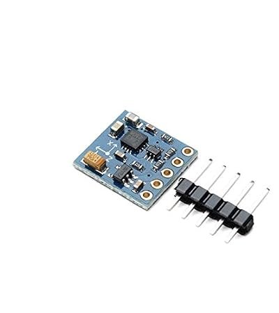
1 x GY-271 QMC5883L 3-Axis Electronic Compass Sensor Module
-
1 x 5-Pin Straight Male Header Strip
Shipping & Delivery
-
Free shipping on orders above ₹999 across India
-
Dispatched within 1-3 business days
-
Expected delivery: 3-7 business days depending on location
-
Secure packaging to ensure safe transit of electronic components
0 Reviews For this Product
Related Products


