
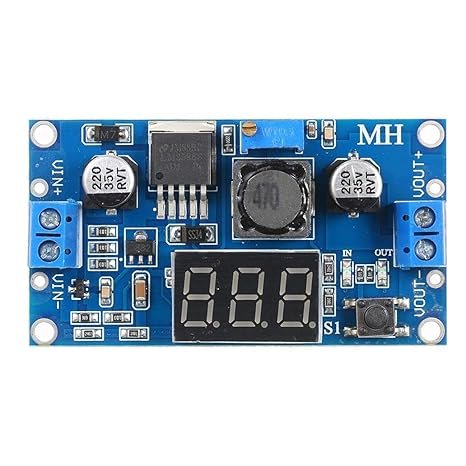


LM2596 DC-DC Buck Step-Down Power Converter Module with Digital LED Voltmeter Display
Step down DC voltage efficiently while monitoring real-time voltage levels with the LM2596 DC-DC Buck Step-Down Power Converter Module with LED Voltmeter. Operating on a wide input range of 4.0V to 40V DC, this versatile switching regulator converts higher input voltages into a smooth, adjustable output voltage from 1.25V to 37V DC. Capable of delivering a continuous current of 2A (3A peak with additional cooling), it features a high-accuracy 3-digit LED display with an interactive touch-button switch to toggle between input and output voltage readings. Complete with screw terminal blocks and an onboard multi-turn precision potentiometer, it eliminates the need for a external multimeter during setup.
₹ 110
₹ 159


The LM2596 DC-DC Buck Step-Down Converter Module with LED Voltmeter combines high-efficiency step-down voltage conversion with a built-in digital display into a single compact board. Utilizing Texas Instruments' monolithic LM2596 switching regulator IC, this module converts higher DC power sources (such as 12V adapters, 24V industrial supplies, or 3S/4S LiPo batteries) into lower regulated DC voltages required by sensitive microcontrollers, sensors, motors, and LED arrays.
Unlike standard buck modules that require a separate multimeter to adjust output voltage, this enhanced version incorporates a 3-digit red LED voltmeter powered by a calibrated microcontroller. A momentary tactile push-button allows users to toggle the display between reading Input Voltage () and Output Voltage (), indicated by onboard status LEDs. The display can also be calibrated for high accuracy or powered off completely to conserve standby power. With integrated thermal shutdown and current limit protection, it provides a stable, reliable power foundation for electronics projects.
Key Features and Benefits
-
Integrated 3-Digit Digital Voltmeter: Built-in red LED display provides real-time voltage monitoring without external test equipment.
-
Wide Voltage Conversion Range: Accepts inputs from to and steps down to an adjustable output from to .
-
High Efficiency Switching Topology: Operates at switching frequency with up to efficiency, generating far less heat than traditional linear regulators (e.g., LM7805).
-
Dual Display Mode & Shutdown: Pressing the function button toggles between input and output voltage display; holding the button turns the LED display off.
-
Dual Connection Options: Equipped with solderless screw terminal blocks as well as large PCB pads for direct wire soldering.
-
Built-in Voltmeter Self-Calibration: Feature-rich firmware allows manual calibration of the voltmeter reading using the onboard push-button.
Technical Specifications
Operation & Voltmeter Calibration Guide
1. Terminal Connections:
-
/ DC Input Power Positive () and Negative Ground ()
-
/ Regulated DC Output Power Positive () and Negative Ground ()
2. Adjusting Output Voltage:
-
Connect a DC power supply () to and .
-
Press the onboard button until the LED lights up (displaying output voltage).
-
Turn the brass screw on the blue multi-turn trimmer potentiometer counter-clockwise to lower output voltage, or clockwise to increase it.
Note: On new modules, turn the potentiometer counter-clockwise 10 to 15 turns if the voltage level does not change immediately.
3. Voltmeter Calibration Procedure:
-
Press the button until the display shows the voltage mode you want to calibrate ( or ).
-
Press and hold the button for over 2 seconds until the display LED flashes rapidly, indicating calibration mode.
-
Short-press the button to increase the reading, or long-press to decrease it (in steps).
-
After calibrating to match a known multimeter reading, press and hold the button for 2 seconds to save settings to memory.
STEP-DOWN OPERATING PRINCIPLE: This is a pure Buck (step-down) converter. The input voltage must be at least higher than the desired output voltage (). It cannot step voltage up.
Applications
-
DIY Benchtop Power Supplies: Creating an adjustable, meter-monitored lab power supply from old 19V laptop adapters.
-
Microcontroller Power Rail Conversion: Stepping down 12V/24V battery systems to for Arduino/Raspberry Pi or for ESP32/STM32 modules.
-
Automotive & Marine Electronics: Running 5V USB chargers or 12V accessory lights from 24V truck or boat electrical networks.
-
LED Driver & Solar Regulators: Powering high-brightness LED arrays and small solar panel voltage stabilization systems.
Package Includes
-
1 x LM2596 DC-DC Buck Step-Down Power Converter Module with Digital LED Voltmeter
Shipping & Delivery
-
Free shipping on orders above ₹999 across India
-
Dispatched within 1-3 business days
-
Expected delivery: 3-7 business days depending on location
-
Secure packaging to ensure safe transit of electronic components
0 Reviews For this Product

Related Products