
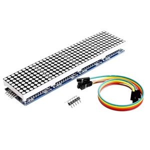
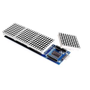

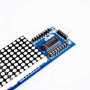
MAX7219 4-in-1 Dot Matrix Display Module 8x32 LED Matrix for Arduino
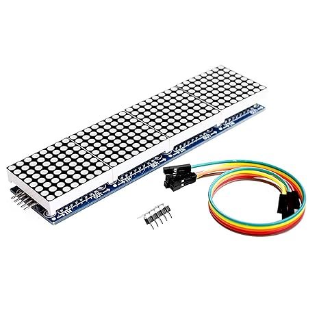
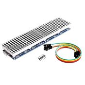
Create dynamic scrolling text displays and custom graphics with the MAX7219 4-in-1 Dot Matrix Display Module. Combining four 8*8 red LED dot matrix units into a seamless 8*32 array, this module is driven by four daisy-chained MAX7219 IC display drivers. Operating on a simple 3-wire SPI communication interface, it allows complete individual pixel control over 256 bright LEDs while using minimal microcontroller I/O pins. Featuring input and output header pins for easy cascading, it is the go-to solution for digital clocks, ticker boards, message displays, and game interfaces powered by Arduino, ESP32, ESP8266, or Raspberry Pi.
₹ 285
₹ 345


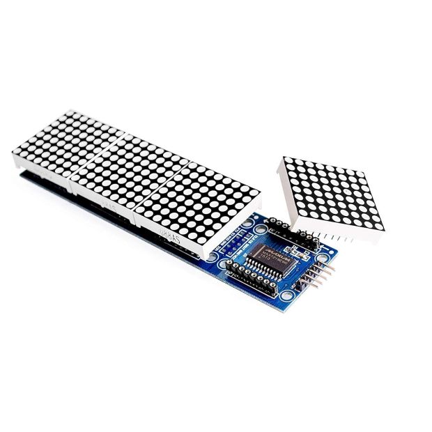
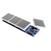
The MAX7219 4-in-1 Dot Matrix Display Module is a integrated multi-digit display system designed for visual messaging and graphic rendering in embedded projects. The board consists of four common-cathode red LED dot matrix modules mounted side-by-side on a single PCB, yielding a total resolution of pixels (256 individual LEDs).
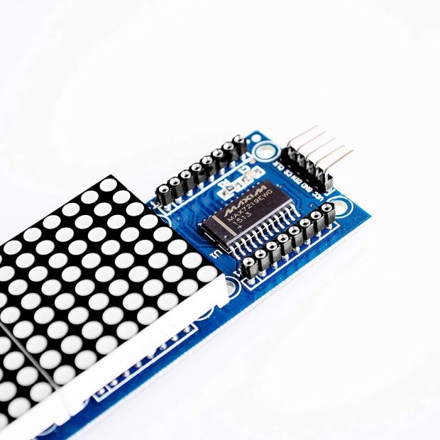
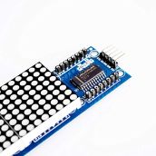
Each matrix block is independently driven by its own onboard MAX7219 serially-interfaced display driver IC. The MAX7219 handles multiplexing, LED current regulation, and brightness control internally, eliminating the need for continuous refreshing from the host controller. Because the four driver chips are pre-wired in series on the module, controlling the entire 256-LED panel requires only 3 digital signal pins (DIN, CS, CLK). Furthermore, the board includes an output header on the opposite side, enabling users to chain multiple 4-in-1 modules together to build arbitrarily long scrolling message displays.
Key Features and Benefits
-
Seamless 8x32 Resolution: Four matrices combined on a single rigid PCB to create a compact active display area.
-
Efficient 3-Wire SPI Interface: Requires only 3 microcontroller digital I/O lines for complete control over all 256 LEDs.
-
Built-In Multiplexing & Memory: Onboard MAX7219 ICs store display data in internal RAM, offloading memory and CPU overhead from the main processor.
-
16-Level Software Brightness Control: Digital brightness adjustment via internal Pulse-Width Modulation (PWM) registers.
-
Expandable / Daisy-Chainable Design: Input and output headers allow chaining multiple 4-in-1 display panels end-to-end without extra signal lines.
Technical Specifications
Pinout & Daisy-Chaining Setup Guide
1. Input Pins (Connect to Microcontroller):
-
VCC: Power Input. -
GND: Power Ground (). -
DIN: Data Input (Connect to MOSI / SPI Data Pin). -
CS: Chip Select / Load Pin (Connect to SS / Digital Pin). -
CLK: Serial Clock Pin (Connect to SCK / SPI Clock Pin).
2. Output Pins (Chain to Next Module Input):
-
VCCVCCof Module 2 -
GNDGNDof Module 2 -
DOUTDINof Module 2 -
CSCSof Module 2 -
CLKCLKof Module 2
POWER ADVISORY: When daisy-chaining more than two 4-in-1 modules ( matrices), power the rail using an external regulated DC power supply rather than drawing power directly from an Arduino's regulator pin.
Arduino Quick-Start Code Example (MD_Parola Library)
Install the MD_MAX72XX and MD_Parola libraries via the Arduino Library Manager:
#include <MD_Parola.h>
#include <MD_MAX72xx.h>
#include <SPI.h>

// Define Hardware Type and Pin Connections
#define HARDWARE_TYPE MD_MAX72XX::FC16_HW // Standard FC-16 module layout
#define MAX_DEVICES 4                     // 4 matrices on the 4-in-1 board

#define CLK_PIN   13
#define DATA_PIN  11
#define CS_PIN    10

// Hardware SPI Connection
MD_Parola myDisplay = MD_Parola(HARDWARE_TYPE, CS_PIN, MAX_DEVICES);

void setup() {
  myDisplay.begin();
  myDisplay.setIntensity(4); // Set brightness level (0 to 15)
  myDisplay.displayClear();

  // Display text: String, Alignment, Speed, Pause, Effect In, Effect Out
  myDisplay.displayText("ELECTROBOAT", PA_CENTER, 100, 2000, PA_SCROLL_LEFT, PA_SCROLL_LEFT);
}

void loop() {
  if (myDisplay.displayAnimate()) {
    myDisplay.displayReset(); // Loop scrolling animation
  }
}
Applications
-
Digital Clocks & Timers: Displaying live time, countdowns, and date strings synced via NTP or RTC modules.
-
Scrolling News & Stock Tickers: Wi-Fi connected ticker displays powered by ESP8266 / ESP32 fetching live API data.
-
IoT Notification Hubs: Displaying incoming emails, social media counters, and weather alerts.
-
Arcade & Retro Gaming Displays: Displaying scores, health bars, and retro arcade game graphics.
Package Includes
-
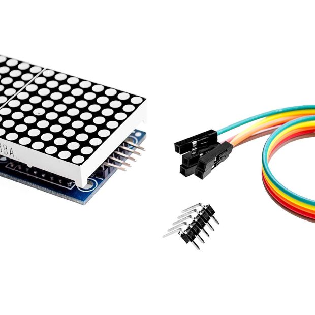
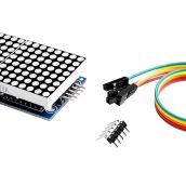
1 x MAX7219 4-in-1 Dot Matrix Display Module ( Red LEDs)
-
1 x 5-Pin Female-to-Female Jumper Ribbon Cable
Shipping & Delivery
-
Free shipping on orders above ₹999 across India
-
Dispatched within 1-3 business days
-
Expected delivery: 3-7 business days depending on location
-
Secure packaging to ensure safe transit of electronic components
0 Reviews For this Product

Related Products