


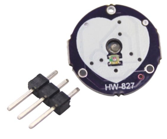
Pulse Heart bit Sensor – Pulse Heart Rate Module Board heart beat sensor
A pulse wave is the change in the volume of a blood vessel that occurs when the heart pumps blood, and a detector that monitors this volume change is called a pulse sensor. The Pulse Sensor is a plug-and-play optical heart rate monitoring module that detects real-time heartbeats by sensing blood flow through the skin. Compatible with Arduino, ESP32, STM32, Raspberry Pi, it’s ideal for fitness wearables, health tracking, and biomedical IoT systems.
₹ 145
₹399
399


: | |
Made In : | India |
Add FAQ
Detailed Description:
Integrate real-time heart rate monitoring into your electronic projects with the compact and user-friendly Pulse Heart Beat Sensor – Pulse Heart Rate Module Board. This innovative sensor allows you to easily detect a person's pulse and transform it into a readable electrical signal, making it an ideal component for fitness trackers, health monitoring systems, interactive art installations, and educational bio-signal processing projects.
The Pulse Heart Beat Sensor operates on the principle of photoplethysmography (PPG). It typically consists of a light-emitting diode (LED) and a photodetector (like a phototransistor or LDR). When a fingertip or earlobe is placed over the sensor, the LED illuminates the skin. As blood flows through the capillaries with each heartbeat, the volume of blood changes, causing a subtle variation in the amount of light absorbed or reflected. The photodetector senses these minute changes in light intensity, generating an analog electrical signal that correlates directly with the pulse wave.
Many of these modules come with onboard amplification and noise cancellation circuitry, ensuring that you get a clean, reliable pulse reading even in noisy environments. This crucial signal conditioning makes it significantly easier to process the data with a microcontroller. The module typically provides an analog output (a fluctuating voltage waveform), which can be directly connected to an analog input pin of microcontrollers like Arduino, ESP32, or Raspberry Pi (via an ADC). Some versions may also offer a digital output or an LED that flashes in sync with each detected heartbeat, providing visual confirmation. The sensor usually operates within a voltage range of 3.3V to 5V DC and consumes very low current (e.g., 4mA at 5V), making it suitable for battery-powered or portable applications. Its plug-and-play design often includes a simple 3-pin interface (VCC, GND, and Signal), making it incredibly easy to integrate into your circuits. For anyone in Pune, Maharashtra, India, or anywhere globally, looking to incorporate biometric pulse data into their creations, this Pulse Heart Rate Module offers an accessible and effective solution.
The Pulse Sensor is an optical biosensor that uses photoplethysmography (PPG) to detect the pulse rate from a fingertip or earlobe. It consists of a light-emitting diode (LED) and a photodetector that measures minute changes in light absorption caused by blood flow.
Designed for easy integration with microcontrollers, it outputs an analog signal that varies with heartbeat intensity. With its plug-and-play design, finger clip, and low power consumption, it’s perfect for DIY heart monitors, fitness wearables, biometric systems, and Arduino-based health projects.
Key Features:
-
Real-time heartbeat pulse detection
-
Plug-and-play module with analog output
-
Works on 3.3V–5V systems (Arduino, ESP, STM32, etc.)
-
Based on optical sensing (PPG) technology
-
Onboard LED and photodetector
-
Noise filter circuitry for stable readings
-
Compact and lightweight for wearables
-
Includes finger strap and 3-pin cable
-
Can be used on finger, earlobe, or wrist
Technical Specifications:
Parameter | Specification |
---|---|
Operating Voltage | 3.3V – 5V DC |
Output Signal | Analog (0–5V pulse waveform) |
Sensor Type | Photoplethysmographic (PPG) |
Interface | 3-pin (VCC, GND, Signal) |
Sampling Rate | ~500Hz (typical with Arduino) |
LED Wavelength | ~600nm (Red) |
Dimensions | ~20mm diameter PCB |
Cable Length | ~25cm (included) |
How to Use:
-
Connect VCC to 5V, GND to GND, and Signal to an analog pin (e.g., A0).
-
Place the sensor on fingertip or earlobe using the included strap.
-
Use an Arduino library like
PulseSensor Playground
to filter and display BPM.
#include
const int PulsePin = A0;
PulseSensorPlayground pulseSensor;
void setup() {
Serial.begin(9600);
pulseSensor.analogInput(PulsePin);
pulseSensor.begin();
}
void loop() {
int myBPM = pulseSensor.getBeatsPerMinute();
if (pulseSensor.sawStartOfBeat()) {
Serial.println("BPM: " + String(myBPM));
}
delay(20);
}
Applications:
-
DIY heart rate monitors
-
Health and fitness wearables
-
Biomedical signal analysis
-
Stress or mood detection systems
-
Arduino-based patient monitoring
-
IoT-enabled fitness systems
-
e-Health and telemedicine projects
Package Includes:
-
1 x Pulse Sensor Module (Round PCB)
0 Reviews For this Product
