
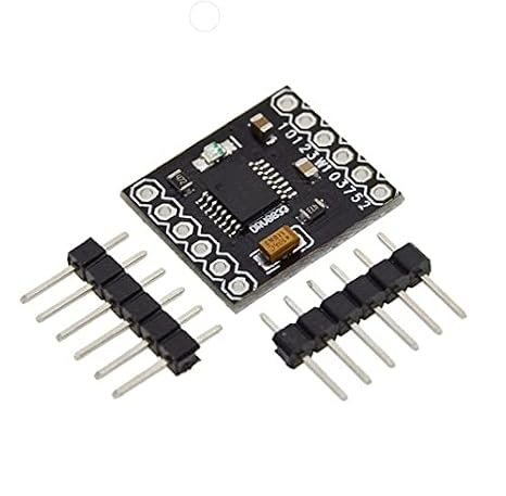
DRV8833 2-Channel Dual DC Motor Driver Module
Power compact, battery-operated robotics and motor control projects with the DRV8833 2-Channel Dual DC Motor Driver Module. Built around Texas Instruments' high-efficiency DRV8833 dual H-bridge IC, this lightweight driver module operates on a wide 2.7V to 10.8V DC supply, making it an ideal low-voltage alternative to bulky L298N or L293D drivers. Delivering up to 1.2A continuous current per channel (2A peak) with ultra-low MOSFET R_DS(on) resistance, it drives two bidirectional brushed DC motors or one 4-wire bipolar stepper motor with minimal power loss and no required heatsink. Fully compatible with 1.8V, 3.3V, and 5V logic levels for seamless integration with Arduino, ESP32, Raspberry Pi Pico, and STM32 microcontrollers.
₹ 70
₹ 108


The DRV8833 2-Channel Dual DC Motor Driver Module is a compact, ultra-efficient H-bridge motor controller engineered specifically for low-voltage, battery-powered embedded robotics. Powered by Texas Instruments' DRV8833 dual MOSFET H-bridge IC, this breakout module replaces power-hungry bipolar drivers like the L298N and L293D by eliminating high internal voltage drops and heavy heat generation.
Operating across a low input range of to , the DRV8833 is tailored for single-cell () or dual-cell () Lithium-Ion/LiPo battery setups as well as battery packs. Each channel provides up to continuous RMS current ( peak pulse) to independently drive two brushed DC motors with forward, reverse, freewheel, and active brake modes. Alternatively, channels can be bridged in parallel to deliver up to continuous output to a single DC motor, or configured to drive one 4-wire bipolar stepper motor. Built-in current limiting, over-temperature protection, and short-circuit shutdown safeguard both the driver chip and host controller.
Key Features and Benefits
-
Ultra-Low Operating Voltage (): Perfect for 1S/2S LiPo battery, cells, and low-power mobile robots.
-
High Efficiency MOSFET Architecture: Integrated low-resistance MOSFET H-bridges () ensure cool operation without requiring bulky external heatsinks.
-
Dual Channel or Parallel Output: Drives two independent DC motors ( each), one bipolar stepper motor, or a single high-power DC motor ( parallel bridge mode).
-
Flexible Logic Level Compatibility: Control inputs respond to logic levels from to , working natively with 3.3V microcontrollers (ESP32, Raspberry Pi Pico, STM32) without level shifters.
-
Ultra-Low Power Sleep Mode: Dedicated pin drops quiescent current consumption down to microamps during standby.
-
Built-in Hardware Protections: Features internal over-current protection (OCP), short-circuit protection, under-voltage lockout (UVLO), and thermal shutdown (TSD).
Technical Specifications
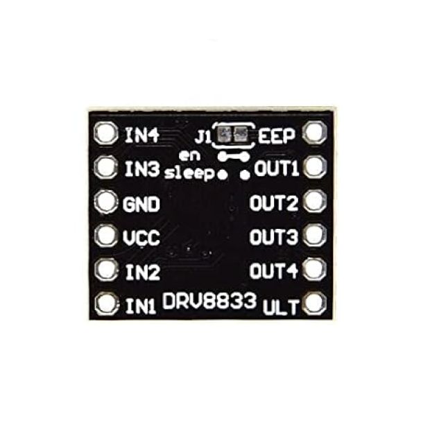
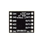
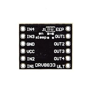
Pinout & Wiring Guide
1. Power & Logic Pins:
-
(): Motor Power Supply Positive Input ( to )
-
: Common Ground () for both motor power and microcontroller logic
-
(): Sleep Mode Input (Connect High / for normal operation; Low / for low-power sleep)
-
: No Connection (Unused pin)
2. Control Inputs (From Microcontroller PWM Pins):
-
& : Inputs for Motor Driver Channel A ( / )
-
& : Inputs for Motor Driver Channel B ( / )
3. Motor Outputs (To Motors):
-
& : Motor A Outputs (Connect to DC Motor 1 or Stepper Coil A)
-
& : Motor B Outputs (Connect to DC Motor 2 or Stepper Coil B)
-
/ : Fault Indicator Output (Active Low on over-current/thermal fault condition)
OPERATION & WIRING ADVISORY:
Ensure the () pin is pulled HIGH ( or ) to wake the IC from sleep mode. Leaving it floating may keep the module in low-power standby mode with outputs disabled.
Always connect the power ground () of your battery/power supply to the ground of your microcontroller board to establish a common signal ground reference.
Applications
-
Miniature & Mobile Robotics: Driving N20 gear motors, TT yellow gear motors, and micro-sumo robot chassis.
-
Battery-Powered IoT Devices: Smart lock actuators, automated curtain openers, and motorized valve controls.
-
3.3V Microcontroller Projects: Directly interfacing motor control with ESP32, Raspberry Pi Pico, and STM32 boards without logic voltage translators.
-
Small Bipolar Stepper Control: Precise position control for mini 4-wire stepper motors in desktop sliders and pan-tilt mounts.
Package Includes
-
1 x DRV8833 2-Channel Dual DC Motor Driver Module
-
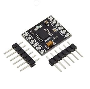
1 x 12-Pin Male Header Strip (Unsoldered)
Shipping & Delivery
-
Free shipping on orders above ₹999 across India
-
Dispatched within 1-3 business days
-
Expected delivery: 3-7 business days depending on location
-
Secure packaging to ensure safe transit of electronic components
0 Reviews For this Product

Related Products