
1.jpeg&width=620&quality=80)
1.jpg&width=620&quality=80)

1.jpeg&width=172&quality=80)
1.jpg&width=172&quality=80)

1.jpeg&width=300&quality=80)
1.jpg&width=300&quality=80)
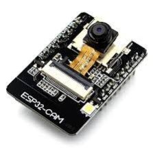
ESP 32 CAM MODULE
ESP32-CAM is a low-cost ESP32-based development board with onboard camera, small in size. It is an ideal solution for IoT application, prototypes constructions and DIY projects. The board integrates WiFi, traditional Bluetooth and low power BLE , with 2 high- performance 32-bit LX6 CPUs.
₹ 508 ₹599
599


Made In : | India |
Add FAQ
The ESP32-CAM module is a compact and versatile development board based on the ESP32 chip, equipped with a built-in camera and Wi-Fi capabilities. It's popular for applications in IoT, surveillance, and image processing due to its low cost and extensive functionality.
ESP32-CAM Module Overview
1. Key Features:
-
Microcontroller:
- Chip: ESP32
- Processor: Dual-core 32-bit Xtensa® LX6 microprocessor
- Clock Speed: Up to 240 MHz
-
Camera:
- Camera Module: OV2640 (or occasionally OV7670 in some variants)
- Resolution: Up to 2 MP (1600 x 1200 pixels)
- Lens: Fixed focus
-
Wireless Connectivity:
- Wi-Fi: 802.11 b/g/n
- Bluetooth: Bluetooth v4.2 (classic and BLE)
-
Memory:
- Flash: Typically 4MB
- RAM: 520 KB SRAM
-
I/O Ports:
- GPIO Pins: Multiple General Purpose Input/Output pins available
- UART: For serial communication
- SPI/I2C: For interfacing with peripherals
- ADC/DAC: Analog-to-Digital and Digital-to-Analog converters
-
Power Supply:
- Voltage: Typically 5V or 3.3V, depending on the module’s power requirements
- Current Consumption: Depends on operating mode and peripherals
-
Additional Features:
- MicroSD Card Slot: For additional storage (varies by module version)
- Onboard LEDs: Often includes a built-in LED for status indication
- Reset and Boot Buttons: For easy module management
2. Pin Configuration:
The ESP32-CAM module usually includes several pins for interfacing with peripherals and other components. Here’s a typical pinout:
- GND: Ground connection
- 5V / 3.3V: Power supply input (check module specification)
- IO0: GPIO0, used for boot mode selection and general input/output
- IO1: GPIO1, often used as a TX pin for serial communication
- IO3: GPIO3, often used as an RX pin for serial communication
- IO4 to IO15: Additional GPIO pins for various functions
- ADC: Analog-to-Digital Converter input
- SD2, SD3: Pins for interfacing with MicroSD card (if available)
- RESET: Resets the module
- FLASH: Flash memory interface
3. Working Principle:
-
Camera Operation:
- The ESP32-CAM uses the onboard camera to capture images or video. The camera module is interfaced with the ESP32 via a dedicated camera interface, allowing the ESP32 to control the camera and process the captured data.
-
Data Transmission:
- Captured images or video data can be transmitted over Wi-Fi to a server, cloud service, or local network for processing, storage, or viewing.
-
Programming and Configuration:
- The module is typically programmed using the Arduino IDE or other development environments compatible with ESP32. It communicates via serial interfaces (UART) for configuration and debugging.
4. Applications:
-
Surveillance Systems:
- Used in security cameras and home surveillance systems for real-time video streaming and image capture.
-
IoT Projects:
- Ideal for Internet of Things (IoT) applications where visual data is required, such as remote monitoring and smart home systems.
-
Image Processing:
- Useful in projects that involve image analysis and processing, such as facial recognition or object detection.
-
Robotics:
- Employed in robotic systems that require visual input for navigation or interaction.
5. Advantages:
-
Integrated Camera:
- Combines a camera with a microcontroller and wireless connectivity in a single module, simplifying design and reducing costs.
-
Wi-Fi Connectivity:
- Provides easy connectivity to networks and cloud services for data transmission and remote access.
-
Versatility:
- Offers multiple GPIOs and interfaces for various peripheral connections, making it suitable for a wide range of applications.
-
Low Cost:
- Provides a cost-effective solution for projects requiring both a camera and microcontroller capabilities.
6. Limitations:
-
Limited Processing Power:
- While capable, the ESP32's processing power is limited compared to more powerful processors, which can constrain complex image processing tasks.
-
Camera Quality:
- The quality of the images captured by the camera may not be as high as more specialized camera modules.
-
Power Consumption:
- Can have higher power consumption when operating Wi-Fi and the camera, which may be a consideration for battery-powered applications.
Example Use Case:
Home Security Camera:
- The ESP32-CAM can be used to build a home security camera system. The camera captures video footage, which is then transmitted over Wi-Fi to a smartphone or computer for real-time monitoring. The module can be programmed to send alerts or capture images based on motion detection.
Summary:
The ESP32-CAM module is a versatile and cost-effective solution for projects requiring a camera combined with microcontroller and Wi-Fi capabilities. Its integration of these features into a single module makes it suitable for applications in surveillance, IoT, and image processing, offering flexibility and ease of use in a compact form factor.

#include "esp_camera.h"
#include
// Camera pin configuration (standard for ESP32-CAM)
#define CAMERA_MODEL_AI_THINKER // Define camera model
#include "camera_pins.h" // Include the camera pins for the specific model
// Wi-Fi credentials
const char* ssid = "your_SSID"; // Replace with your Wi-Fi SSID
const char* password = "your_PASSWORD"; // Replace with your Wi-Fi password
// Web server port and path
WiFiServer server(80); // HTTP server runs on port 80
void startCameraServer() {
server.begin();
Serial.println("Camera server started");
}
void setup() {
// Start serial communication
Serial.begin(115200);
// Connect to Wi-Fi
WiFi.begin(ssid, password);
Serial.println("");
while (WiFi.status() != WL_CONNECTED) {
delay(1000);
Serial.print(".");
}
Serial.println();
Serial.println("Connected to Wi-Fi");
Serial.print("IP Address: ");
Serial.println(WiFi.localIP());
// Initialize the camera
camera_config_t config;
config.ledc_channel = LEDC_CHANNEL_0;
config.ledc_timer = LEDC_TIMER_0;
config.pin_d0 = 12;
config.pin_d1 = 13;
config.pin_d2 = 14;
config.pin_d3 = 15;
config.pin_d4 = 16;
config.pin_d5 = 17;
config.pin_d6 = 18;
config.pin_d7 = 19;
config.pin_xclk = 21;
config.pin_pclk = 22;
config.pin_vsync = 23;
config.pin_href = 25;
config.pin_sscb_sda = 26;
config.pin_sscb_scl = 27;
config.pin_pwdn = 32;
config.pin_reset = -1; // No reset pin
config.xclk_freq_hz = 20000000;
config.frame_size = FRAMESIZE_QVGA;
config.pixel_format = PIXFORMAT_JPEG;
// Initialize the camera
esp_err_t err = esp_camera_init(&config);
if (err != ESP_OK) {
Serial.printf("Camera init failed with error 0x%x", err);
return;
}
// Start the camera server
startCameraServer();
}
void loop() {
WiFiClient client = server.available();
if (!client) {
return;
}
// Wait for the client to send a request
Serial.println("New Client.");
while (!client.available()) {
delay(1);
}
// Send HTTP headers
client.println("HTTP/1.1 200 OK");
client.println("Content-Type: multipart/x-mixed-replace; boundary=frame");
client.println();
// Stream the video feed to the client
while (client.connected()) {
camera_fb_t *fb = esp_camera_fb_get();
if (!fb) {
Serial.println("Camera capture failed");
return;
}
// Send the frame to the client
client.println("--frame");
client.println("Content-Type: image/jpeg");
client.println("Content-Length: " + String(fb->len));
client.println();
client.write(fb->buf, fb->len); // Send the frame
client.println();
// Release the frame buffer back to the pool
esp_camera_fb_return(fb);
}
// Close the connection
client.stop();
Serial.println("Client Disconnected.");
}
0 Reviews For this Product
